Project 08
Wind turbine BEM model.
A blade element momentum model of a 100 m wind turbine rotor, written in MATLAB. The blade is split into 500 annular rings and the code solves for the axial and tangential induction in each one, then sums them for the rotor's power and power coefficient.
Setup
Inputs and results
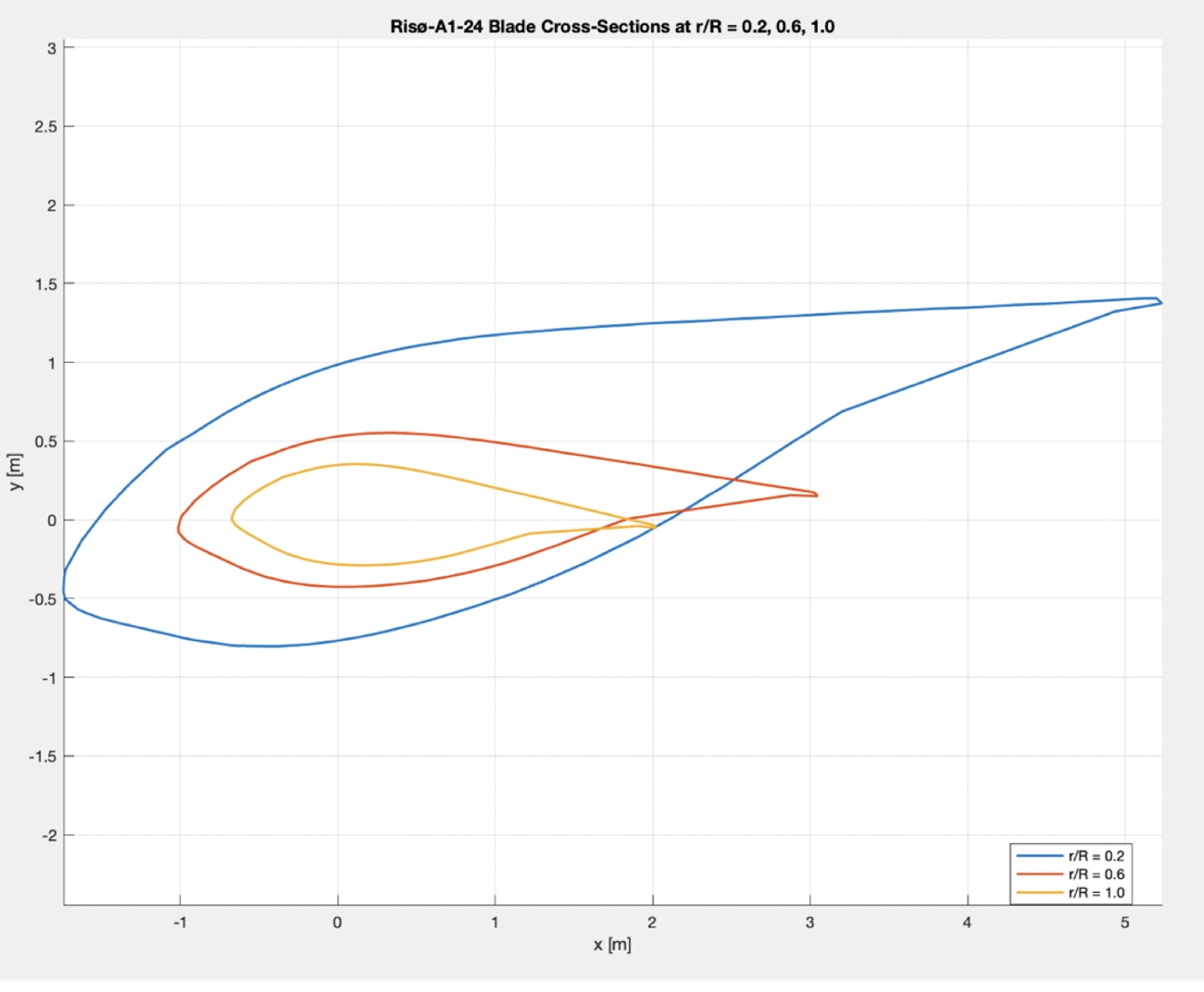
The blade uses the Risø-A1-24 airfoil, with solidity and twist read from a spanwise geometry table and lift and drag interpolated from airfoil data.
| Tip speed ratio | 7 |
|---|---|
| Tip radius | 50 m |
| Blades | 3 |
| Inflow velocity | 8 m/s |
| Air density | 1.225 kg/m³ |
| Annulus rings | 500 |
| Power coefficient, Cp | 0.5117 |
|---|---|
| Power | 1260.219 kW |
| Tip Mach number | 0.163 |
| Rotational speed | 10.70 rpm |
A Cp of 0.5117 is high but sits below the Betz limit of 0.59. Real turbines usually land near 0.45 once mechanical and turbulent losses are counted, and this model leaves those out, so 0.51 is reasonable. 1.26 MW at 8 m/s from a 100 m rotor is also realistic — machines this size are typically rated 2–3 MW, but at 11–12 m/s. A tip Mach number of 0.163 means compressibility can be ignored.
Results
Where the power comes from
Power density peaks around the middle of the blade, not at the tip.
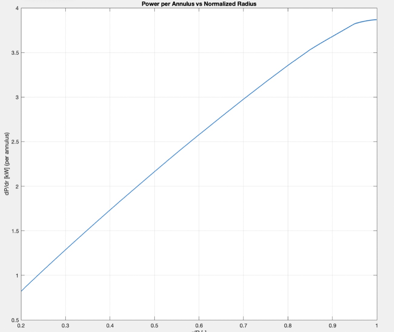
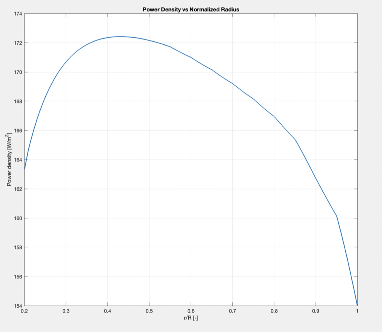
Tangential velocity grows with radius, so torque climbs steadily outward. But chord and solidity shrink toward the tip to cut mass, centrifugal load and tip vortex strength. The two effects cross in the midspan, which is where power density is highest, around r/R = 0.4 to 0.6.
Near the root the blade is thick and highly twisted but moving slowly, so it contributes little power — that region is sized for strength. Near the tip the speed is high but the section is slender, so the local torque falls off again.
MATLAB. Coursework for ME 5427 Turbomachinery at Ohio State, autumn 2025.
© 2026 Jay Chung